Automated Wheel Truing Stand Part 3
In my last blog post I outlined the electronics I used for this project and in this post, I will continue to describe the semi-automated wheel truing process.
Stage 2 continued: Semi-automated wheel truing process
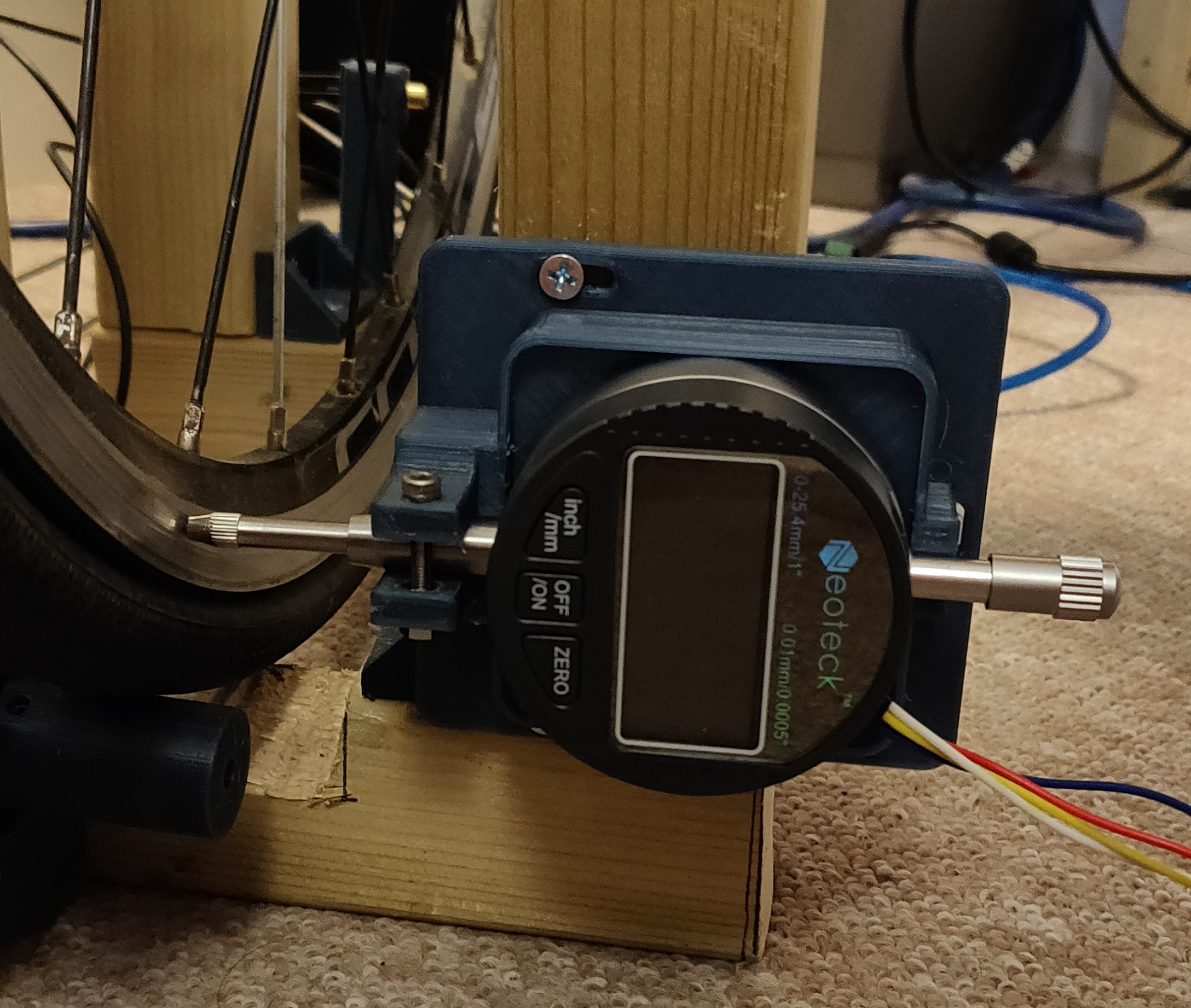
After testing the DTI serial communication, I mounted the DTI to the stand and modified the Arduino code to output the value of the DTI when requested.
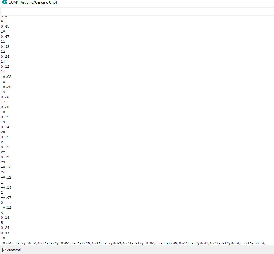
I then created an algorithm to gather the deflection value of the rim at each spoke. To do this, I used my "Go to spoke" algorithm to go to each spoke sequentially, pause for a short time to ensure there were no residual vibrations, and read the deflection value from the DTI.
After gathering all of the deflections, the algorithm returns the largest absolute deflection to the Arduino serial monitor and then presents the spoke with the worst deflection for the user to adjust.
For adjustment, the serial monitor outputs the turn required (e.g. 1/4 turn) in the direction required (e.g. tighten/loosen - clockwise/anticlockwise). Tightening the spoke pulls the rim to the side of the hub where the spoke is attached whereas loosening it does the opposite. The required adjustment depended on the absolute value of the deflection so large deflections corresponded to large adjustments.
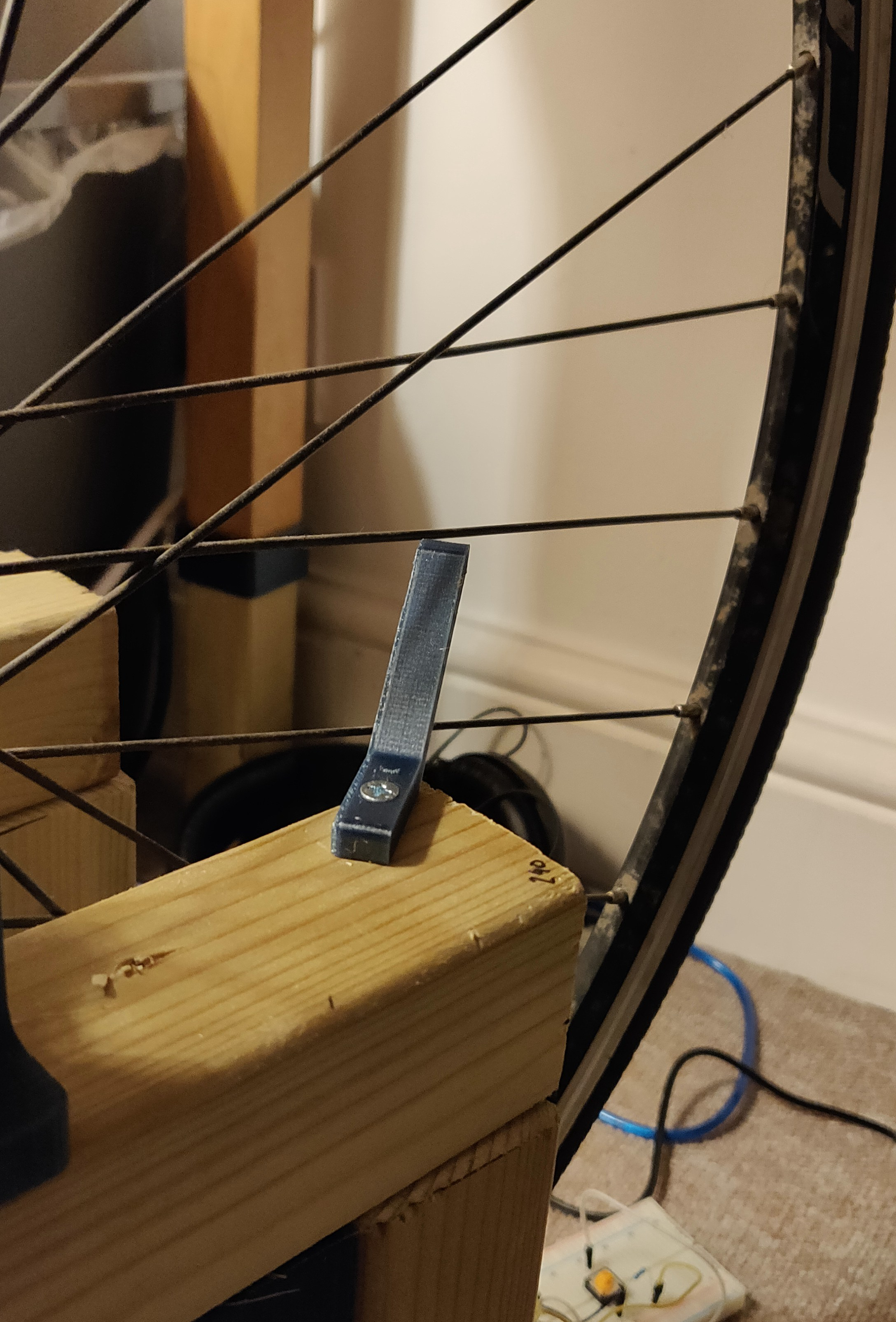
To allow easy adjustment of the worst offending spoke, the adjustment offset was set to be 5 spokes from the detector. I 3D printed a simple indicator to show which spoke requires adjustment, however, this did not work as intended as the distance differs depending on which side of the hub the spoke is attached. The final solution will have automated spoke adjustment so I did not get around to fixing this issue and I counted the offset manually instead.
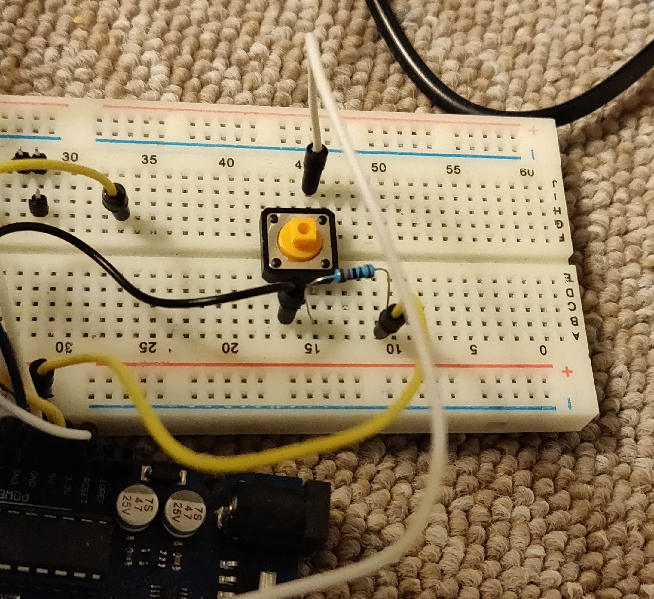
To allow the truing process to continue, I added a push button to the circuit which should be pressed after the spoke has been adjusted. Pushing the button gathers all of the deflections of each spoke again and presents the user with the new worst spoke and the instruction on how to adjust it.
As this process is repeated over many spokes and the deflections decrease, the adjustment becomes finer and finer until all deflections are within a +/- 0.5mm range, which is deemed acceptable according to research I did on wheel truing.
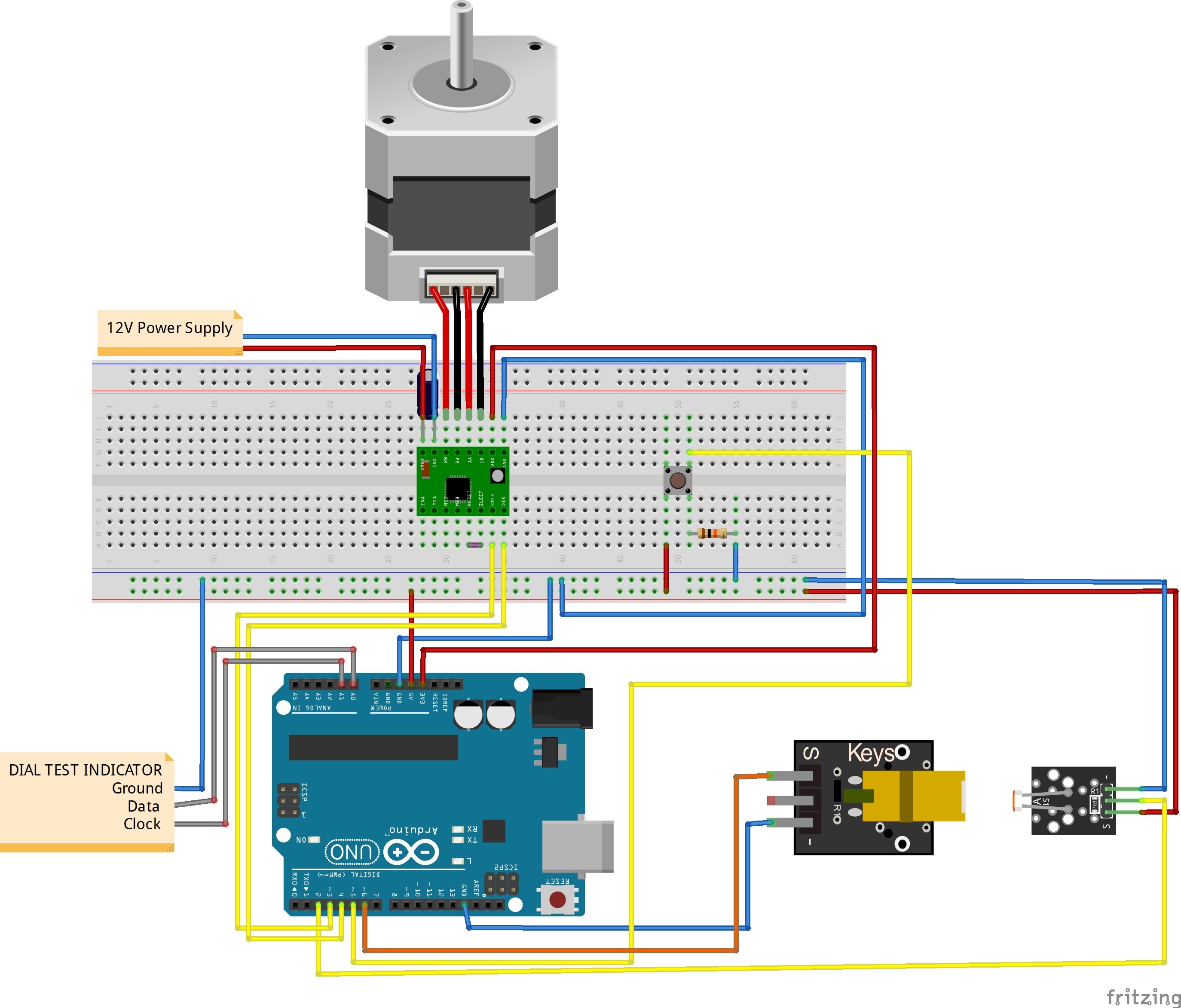
The final circuit is shown below.
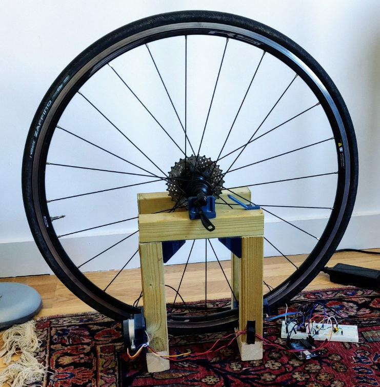
The below image shows the final proof of concept setup with my wheel mounted on the stand. My very broken old wheel was lost when I moved house so I had to use my new one instead. I had to modify the code to account for 24 spokes instead of 32 and add spacers to the laser sensor bracket to increase the offset distance between the laser and DTI. This will be a user input and a mechanical adjustment in the next iteration.
Python plots
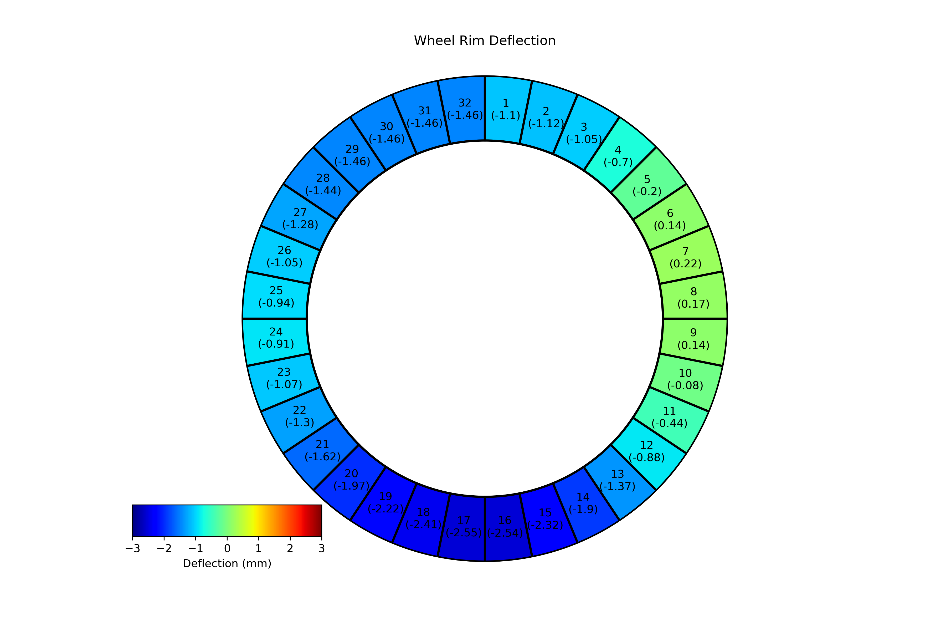
To visualise what was going on with the wheel deflection values, I created some plots in Python using matplotlib. It took a while for me to think of the best way to present the results (initially I was thinking of rotated 3D plots) but in the end, I thought a side view of the rim would be best. I created the first plot using matplotlib in Python using a colour bar to indicate the magnitude of the deflection at each spoke position. A positive value signifies a deflection towards the DTI, whilst a negative value signifies a deflection away from the DTI. Green indicates the rim is "trued" whilst dark blue and dark red indicate an "untrued" value.
This was the first set of results that I got from my first successful run on my old wheel with the DTI measuring the deflection at each spoke position.
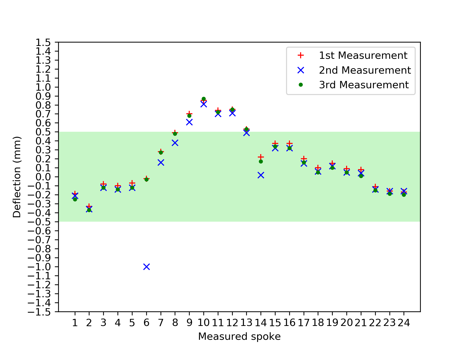
I then investigated how repeatable my measurements were. To do this, I ran the "gather deflections" algorithm three times without adjusting any spokes, and recorded the deflections. As the next plot shows, the system is quite reliable although there was one anomalous result on spoke six that requires further investigation into the reason behind the anomaly. The average standard deviation was calculated at 0.031mm excluding the deflection values from spoke 6. The green band indicates the acceptable range of where the deflection values can lie for the wheel to be trued.
After ensuring the system was fairly repeatable, I carried out the first full truing operation. I already knew that my new wheel was reasonably true except from the one high spot that was observed from spinning it in my bicycle frame and as can be seen on the repeatability plot.
The following GIF shows the entire truing process with each image representing the state of the deflections, proceeding to the next image which shows its new state after adjusting the spoke with the greatest deflection value.
As can be seen, the semi-automated wheel truing process was somewhat successful, with the image going from yellow to green (albeit with a couple of anomalous results) producing a final worst deflection value of -0.52mm. This was close enough to the 0.5mm threshold I had set as I was running out of time before moving abroad.
Errors and uncertainties and future work
I will lay out some error inducing areas which need to be resolved in the next iteration as well as future improvement on the path to full automation.
Measurement error
One potential area that could cause an error is the wear groove that is present on most bicycle wheel rims. Due to the way that the DTI probe is running along the wheel rim, this could introduce an error at some spoke positions, however, due to the low impact in deflection deviation, it may not be worth considering or rectifying.
Stand
The stand material and construction is obviously less than perfect for this application. The wood was cut by hand meaning the stand is not as square as it could be and will deflect with a relatively small load. For the next iteration of the wheel truing stand, I think I'm going to get some 40mm x 40mm aluminium extrusions for improved stiffness and a lot of t-slot nuts to fit all of the bracketry.
Spoke tension
This is something that I knew would be an issue from the start. Without ensuring the spoke tension is sufficient for each spoke, the wheel could be completely true but the spoke tension could be too low, meaning that as soon as the wheel is used on a bicycle, it could immediately lose its "trueness". A future improvement would be a clever way of measuring the tension of each spoke of the wheel but this requires further thought on how this will be achieved.
Noise
When gathering deflection values, occasionally (approximately 1 in 20 results) the returned value would be wildly incorrect giving a deflection of 10s to 1000s of mm. My current method of rectifying these incorrect values was to drive the motor to reverse the wheel and retake the measurement until it was below 5mm absolute deflection. This is a less than ideal solution, so I will further investigate the cause of this noise which could be data processing errors or signal noise of some kind.
Adjustment
To allow for different sized wheels, I will incorporate some level of adjustment in the stand such as sliding brackets for the DTI, laser sensor and motor, perhaps with t-slot nuts and quick adjustment knobs.
As well as this, the number of spokes can vary from wheel to wheel so the user interface could be enhanced, possibly with a display and input to allow the user to enter different values.
Accuracy
I may add an additional DTI on the opposite side of the rim to offer some redundancy and potentially increase the accuracy of the measurements.
Full automation
The end goal of the project is to have a fully automated system. This will require a mechanism to adjust the spokes. I think this will be the most technically challenging part of the project to ensure that it is reliable and has the minimum number of actuators and minimum power requirements. It may also require a camera or another sensing device to capture the spoke nipple orientation to determine the approaching angle of the tightening mechanism.
Vibration and audible noise reduction
Currently, the stepper motor uses an A4988 stepper driver which works well but is quite noisy and causes a lot of vibrations in the system. I may replace this with a silent stepper driver which has become available in the last few years due to noise reduction in 3D printers. This should reduce the audible noise and vibrations of the system significantly.
Speed
I may introduce some gearing to increase the speed of wheel rotation because it currently operates at a snail's pace.
Conclusion
I'm pretty happy with the project so far and look forward to creating a fully automated solution with the improvements stated above when I have the time.
Contact Me About This Post
Subscribe to Blog Updates
Enter your email to receive notifications when new posts are published.