Automated Wheel Truing Stand Part 2
In my last blog post, I built a proof of concept prototype for the wheel truing stand. In this blog post, I outline the electronics I selected and programmed as well as the mounting brackets I designed.
Stage 2: Electronics
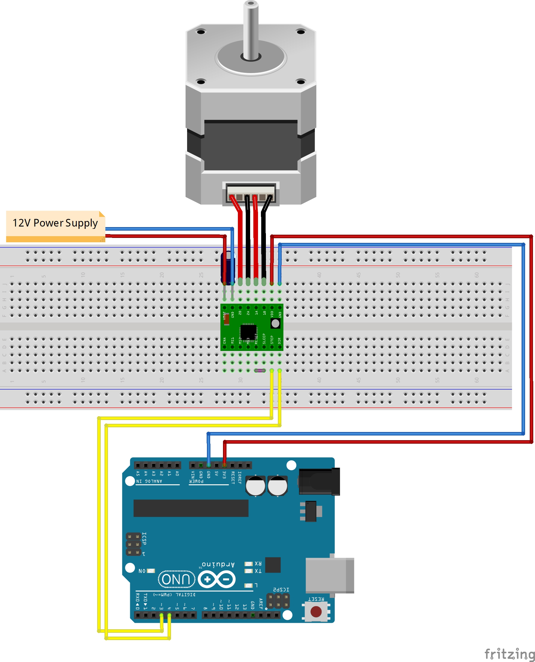
I selected a spare A4988 stepper motor driver from my 3D printer build which would be suitable to drive the NEMA 17 stepper motor. I chose an Arduino Uno to control it and got an 8A 12V DC power supply that would be suitable to power the motor and any additional hardware I would need. I created the following circuit to start things off, using Fritzing to create the electronics CAD diagram.
With the motor now in motion, I had to develop a way for the system to know what position the wheel was in during its rotation. I realised that each spoke around the wheel was approximately equidistant from the spoke next to it, except from the inner tube valve that was in between two of the spokes.
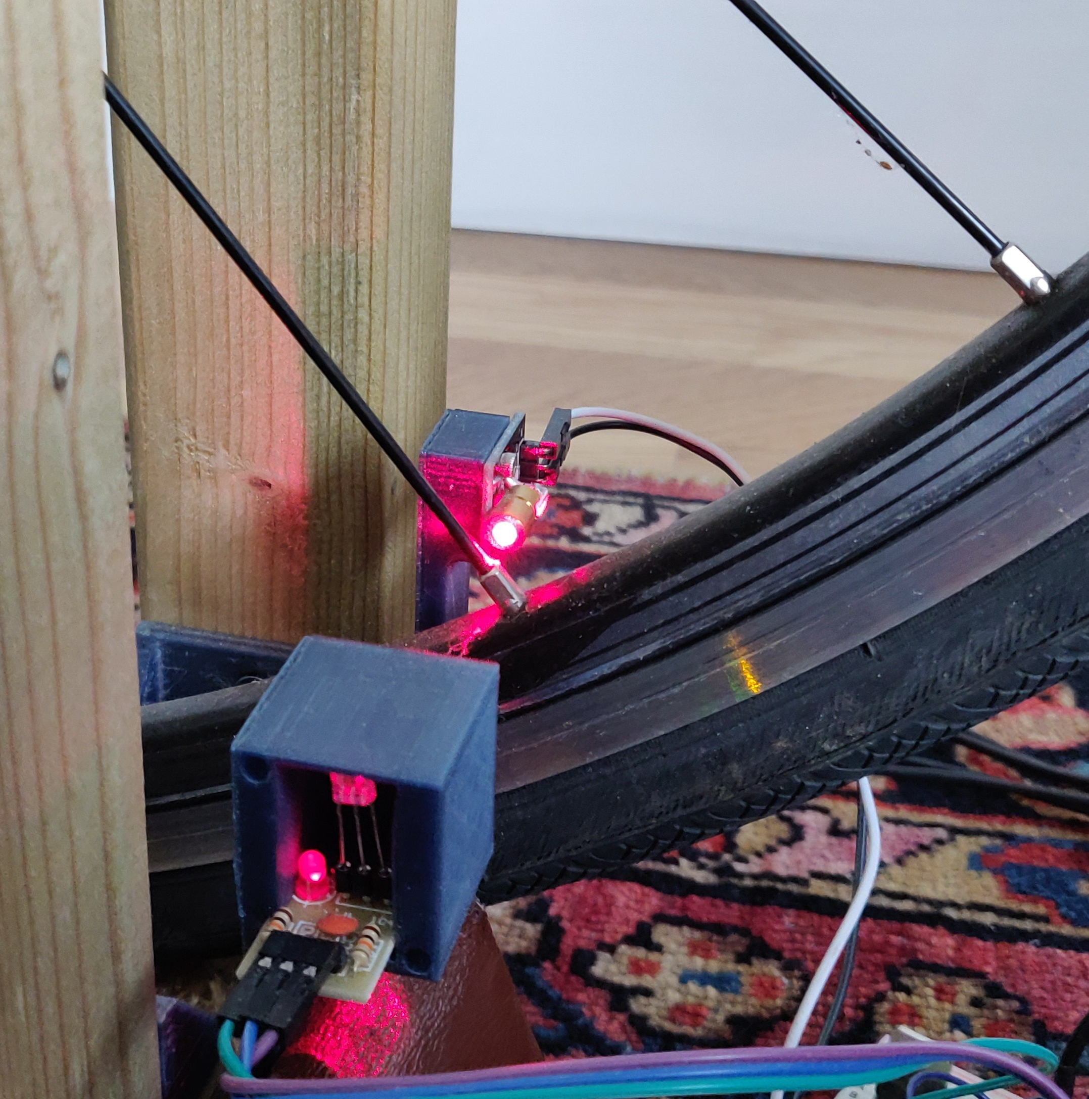
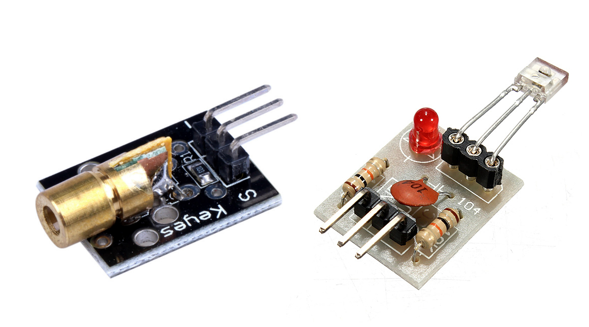
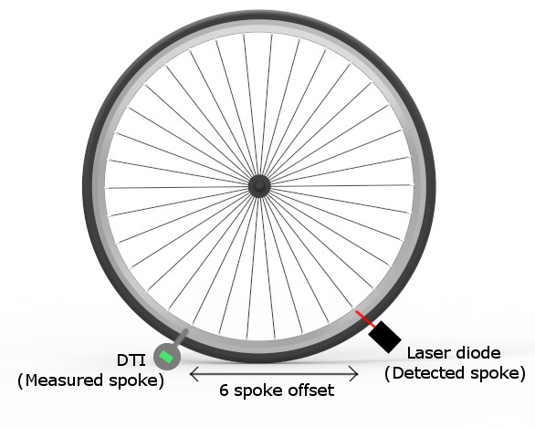
I decided to use a cheap laser diode which I made sure had a beam diameter smaller than the width of each spoke nipple, and a corresponding laser sensor that would measure ON or OFF. This would allow me to detect each spoke or the valve as the wheel rotated and "broke" the beam, acting as a laser tripwire.
To mount the laser diode and sensor to the wooden stand, I designed and 3D printed a mounting bracket which would allow for some post-assembly adjustment and enclose the sensor so it would not be affected by changes in external lighting conditions.
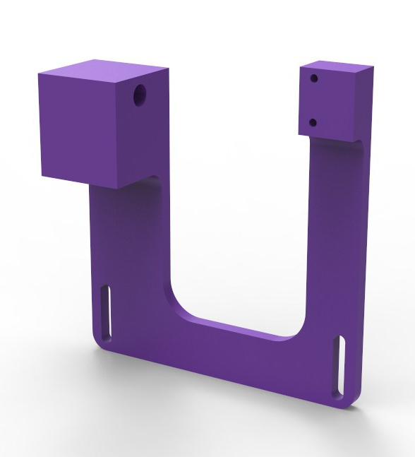
I wired up the laser diode to be constantly ON and mounted the bracket to the stand. I found that the enclosure was sufficient so that laser detection during varying external light conditions was not affected.
With the motor, laser diode and sensor wired up to the Arduino, I created an algorithm to count the number of discrete steps the stepper motor made between each detected point (spoke or the valve), noting that the two smallest step counts would be the gaps between the valve and the spokes next to it. I used the previous and present value of the laser sensor after each step to determine whether the system was either in a gap, on a point or at the beginning or end of a point.
I used the Arduino Serial monitor to debug the system.
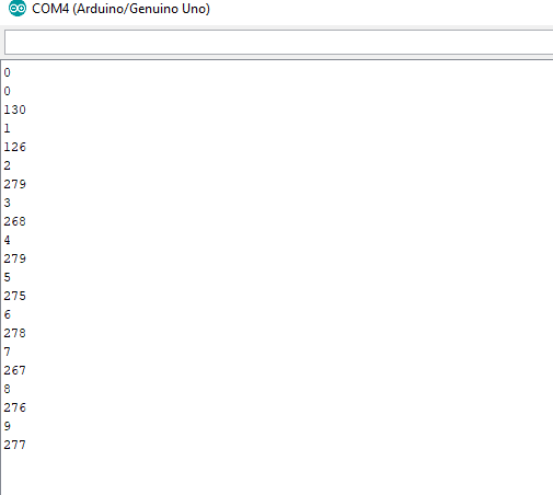
After completing one full revolution (33 points detected), the algorithm could find the two smallest gaps. Then it would determine the position of the valve, and use the most efficient route to get there, find the centre point and then stop. At this point, the system is in the zero position and has homed.
To home the wheel, I found that it was not possible to just use the number of steps counted from the detected valve position to get back to the valve (do the reverse number of steps) as any varying slip on the tyre could cause the system to lose steps. I improved the reliability of the homing algorithm by getting the program to count each point instead, which worked every time.
After defining the zero position, I created a "Go to spoke" algorithm, which could move the wheel to any specified spoke, numbered clockwise from 1 to 32 from the valve, in the most efficient direction (clockwise or anti-clockwise).
The following animation shows a test of the "Go to spoke" algorithm, going from spoke 18 to spoke 2 then from spoke 2 to spoke 0 (the valve).
To measure the deflection of the wheel and measure how "un-true" it was, I bought a cheap digital dial test indicator which claimed to have RS232 serial communication capabilities. After doing some initial research online, I came across this hackaday post where someone had used a very similar (if not the same) DTI and successfully communicated with it.
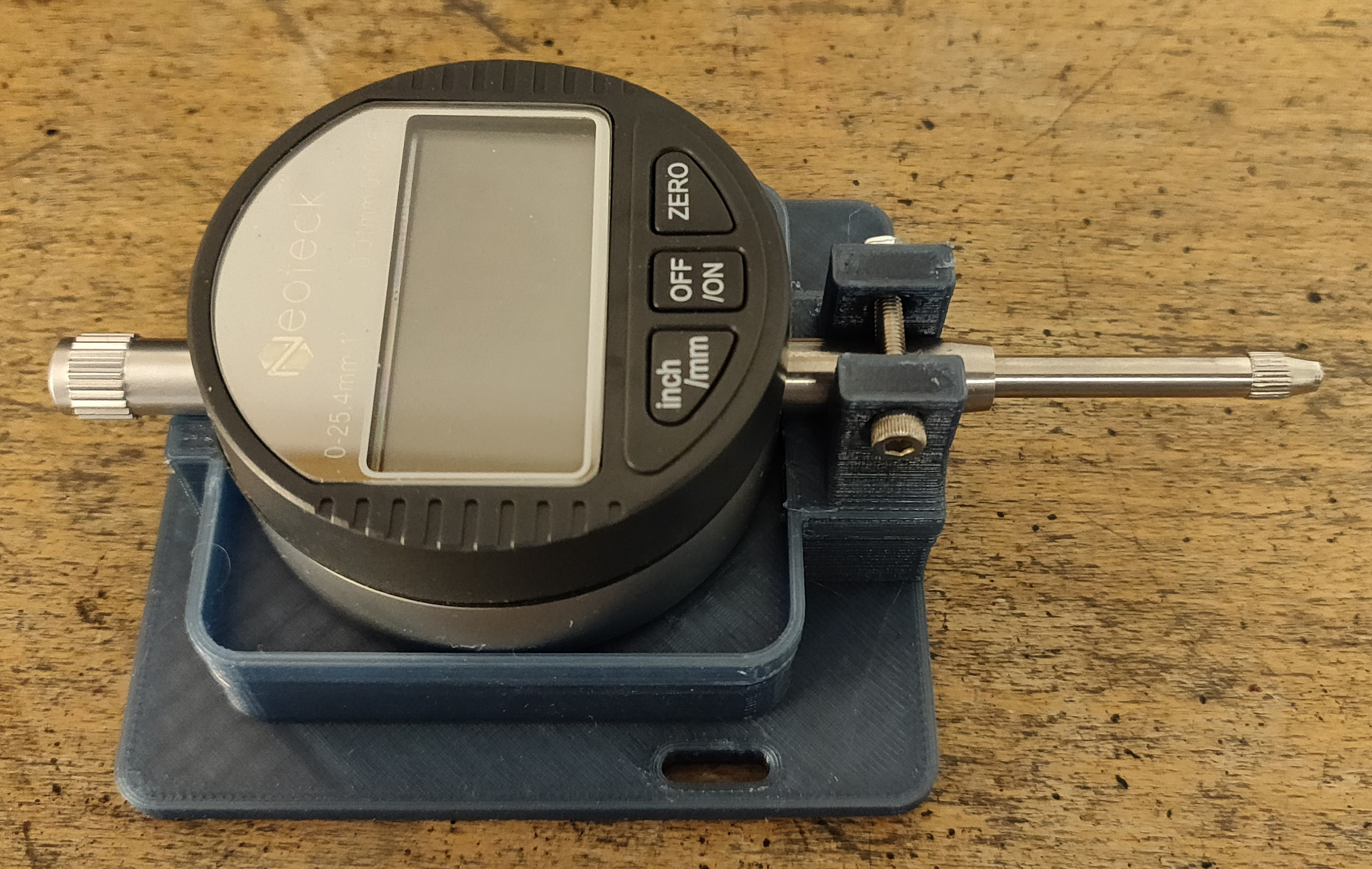
I designed and 3D printed a DTI mount to hold the DTI in position, perpendicular to the wheel rim, and ensured that the plunger of the DTI lined up with a spoke when the laser was in line with a spoke nipple. As the measured spoke was not the spoke being detected, a measuring offset of 6 spokes was entered into the Arduino code.
To calculate the "perfect" position of the rim, I made an assumption that the stand was perfectly square and that the wheel was in the perfect centre of the stand, thus giving the "perfect" deflection value of the DTI.
I then took the DTI apart to solder four wires to the communication pads for Serial communication. This was by far the hardest soldering I had ever attempted resulting in me breaking the first DTI, possibly by introducing too much heat into the PCB.
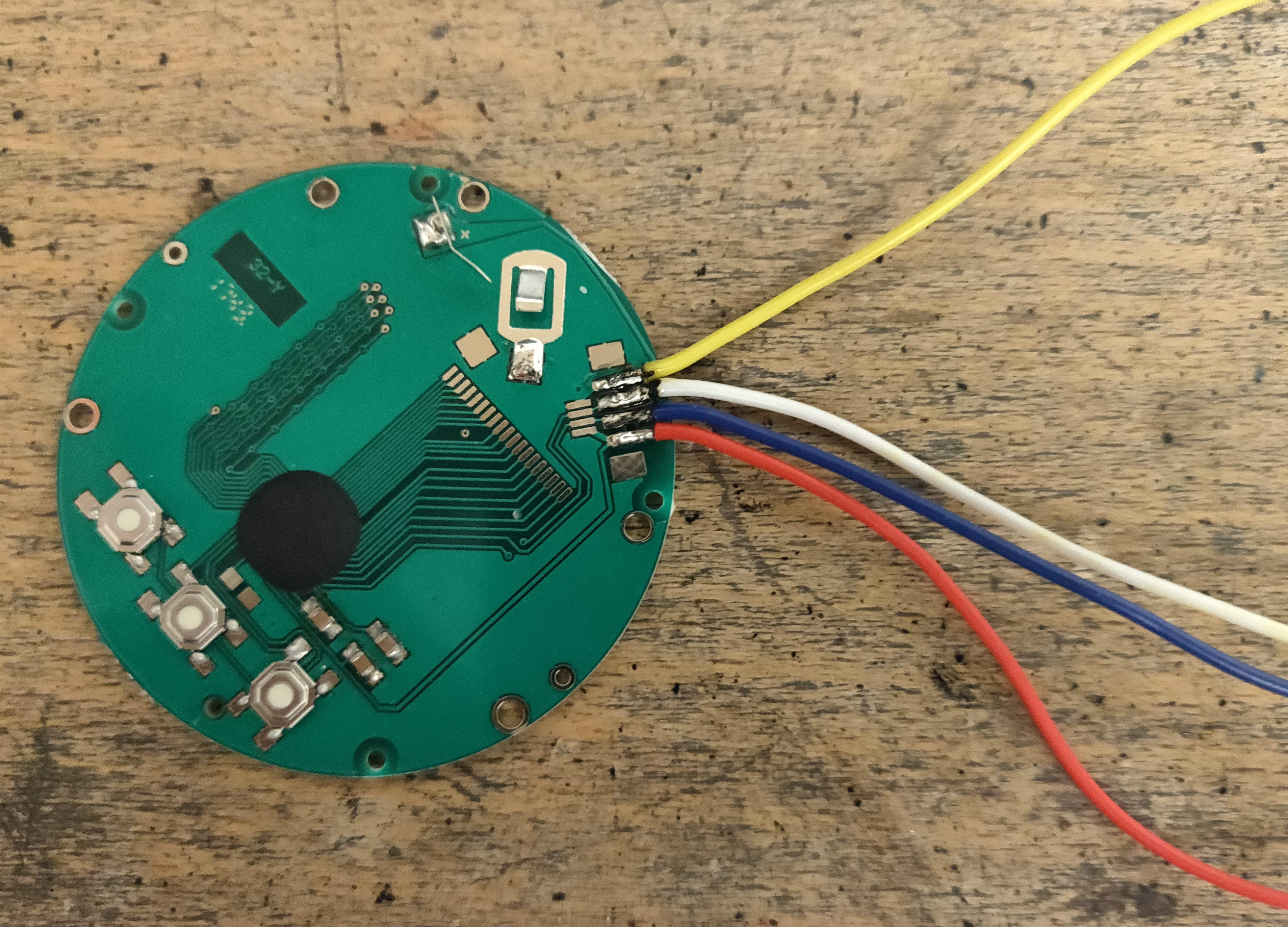
Having ordered a new DTI and a better soldering iron, I successfully soldered the joints and used some electrical tape to reinforce the connections around them. After reassembly, the DTI displayed the results as intended.
I had done some research online and found a project that had Aduino code which allows communication with this type of DTI. I connected the DATA and CLOCK pins to analogue inputs on the Arduino and the ground pin to ground, uploaded the code and it worked!
The next blog post will continue to outline the development of the semi-automated wheel truing process.
Contact Me About This Post
Subscribe to Blog Updates
Enter your email to receive notifications when new posts are published.