Automated Wheel Truing Stand Part 1
Background
I used to commute every day to work (~18km) and used heavy panniers on the pothole filled roads of London. After a year with this kind of commute – plus a France cycle tour (~1000km), my rear wheel had had enough. A spoke broke on my cycle tour and I was put in the position of either replacing the wheel or re-truing it.
I opted to buy some new spokes, replace the broken one and re-true it using my frame and brake pads as a guide. This was both not that fun and took quite a bit longer than I would have liked! I’d been thinking about doing a new automation project and an idea popped into my head; what if I could place the wheel in a machine that would do all of this for me and I would never have to worry about re-truing my wheel again? And so the project began.
Goal
Create a fully automated bicycle wheel truing stand that will true a wheel with no human intervention.
Stages:
Stage 1
- Generate concept designs of the system, create 3D CAD model and build a cheap proof of concept prototype.
Stage 2
- Wire electronics and write code to enable a semi-automated process with the stand recording how untrue the wheel is and directing the user to tighten the correct spokes in the correct order.
Stage 3
- Create concepts of automated spoke tightening mechanism and test.
Stage 4
- Assemble final prototype and amalgamate all aspects of the machine.
Stage 1
- Generate concept designs of the system, create 3D CAD model and build a cheap proof of concept prototype.
I realized the system would require a few fundamental features to work:
- A stiff frame to secure the wheel, preferably positioned in the same way each time.
- A way of measuring the deflection of the un-true rim.
- A method of the machine knowing the wheel's position and the position of the spokes.
- A method of rotating the wheel.
- A method to tighten each spoke and ensure tension is correct and consistent.
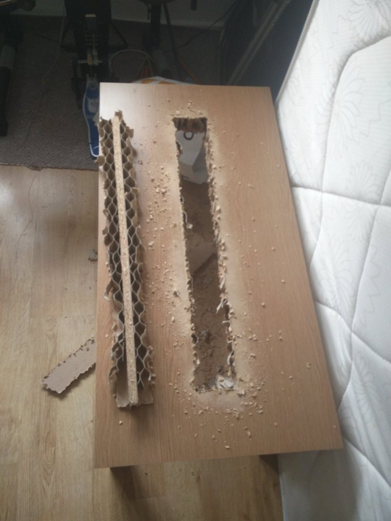
To build a quick and dirty proof of concept prototype, I needed a frame that would both secure the wheel and facilitate the mounting of additional hardware. I found what I thought was a hardwood table of the right size locally on Gumtree and cut a slot out of the middle of it. First mistake. The centre had a single stiffening element but the remainder was just corrugated cardboard rendering the table completely useless as it had lost its stiffness entirely.
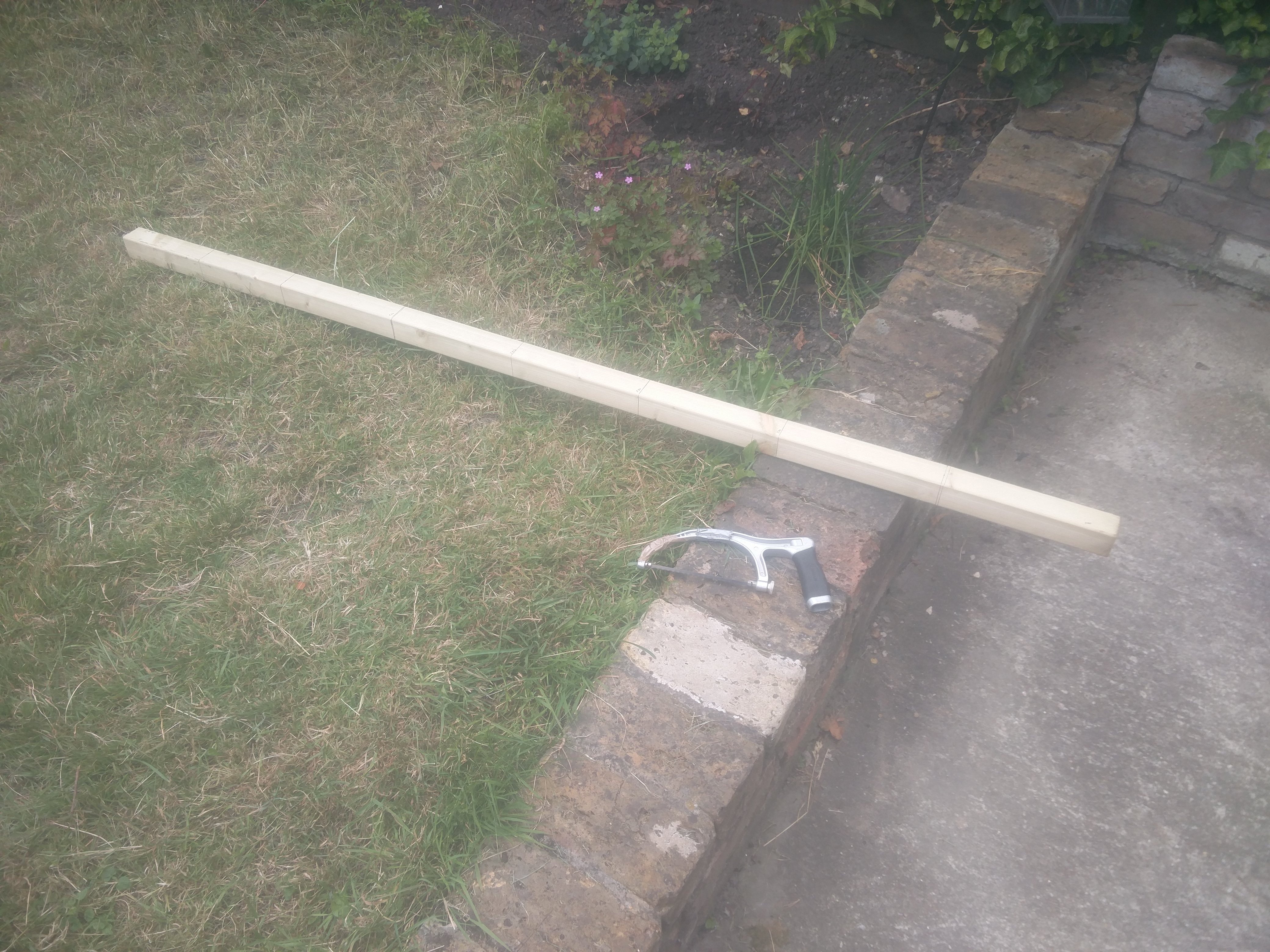
Luckily, I had a spare 1.76m length of wood (50mm x 50mm cross-section) that was reasonably stiff and would allow me to easily modify the stand and mount hardware. The only issue was that I had a limited length and didn't want to buy more material so I designed the prototype with that in mind.
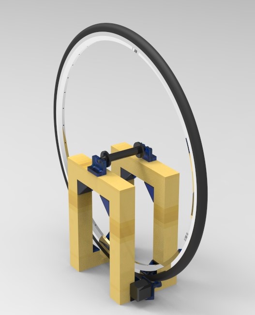
After measuring and modeling my old wheel, I designed a basic frame with the available wood I had and designed brackets that I planned to 3D print. I designed a mount for a spare NEMA 17 stepper motor I had, mounts for the wheel and some angle brackets to keep everything square and make up for my less than perfect hand sawing.
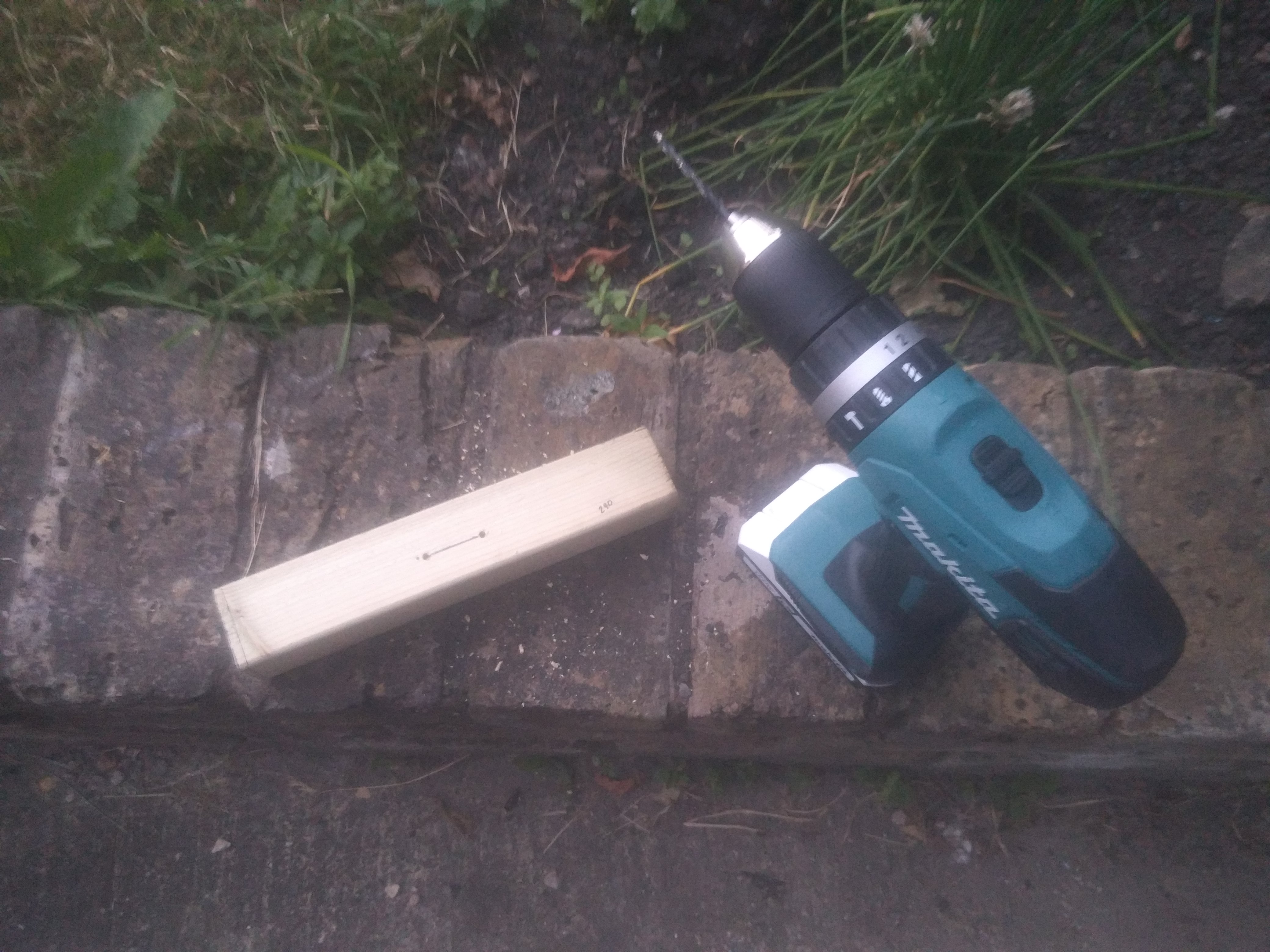
From here, I marked and cut down my length of wood and marked up and drilled the pilot holes for the mounts and brackets.
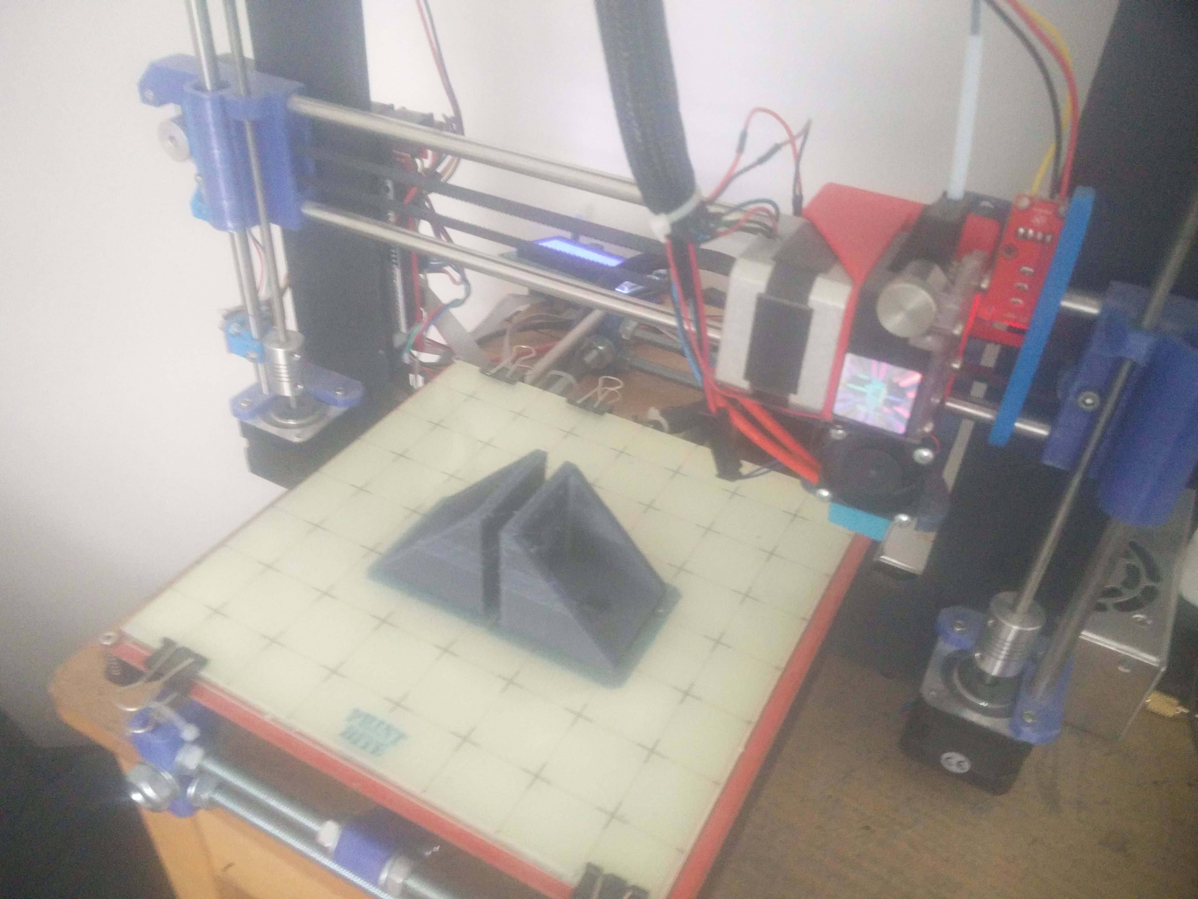
Then I 3D printed the mounts and angle brackets in PETG on my home-built RepRap Prusa i3 3D printer (blog to follow) over the course of a few evenings. I've been using PETG exclusively for a while now and it has been great. It has the strength and rigidity of ABS and it is about as easy to print with as PLA.
I used some cheap wood screws to screw everything together and mounted my old untrue wheel. I immediately realized that I'd based the width of the wheel hub of my front wheel which was 30mm narrower than my rear wheel hub.
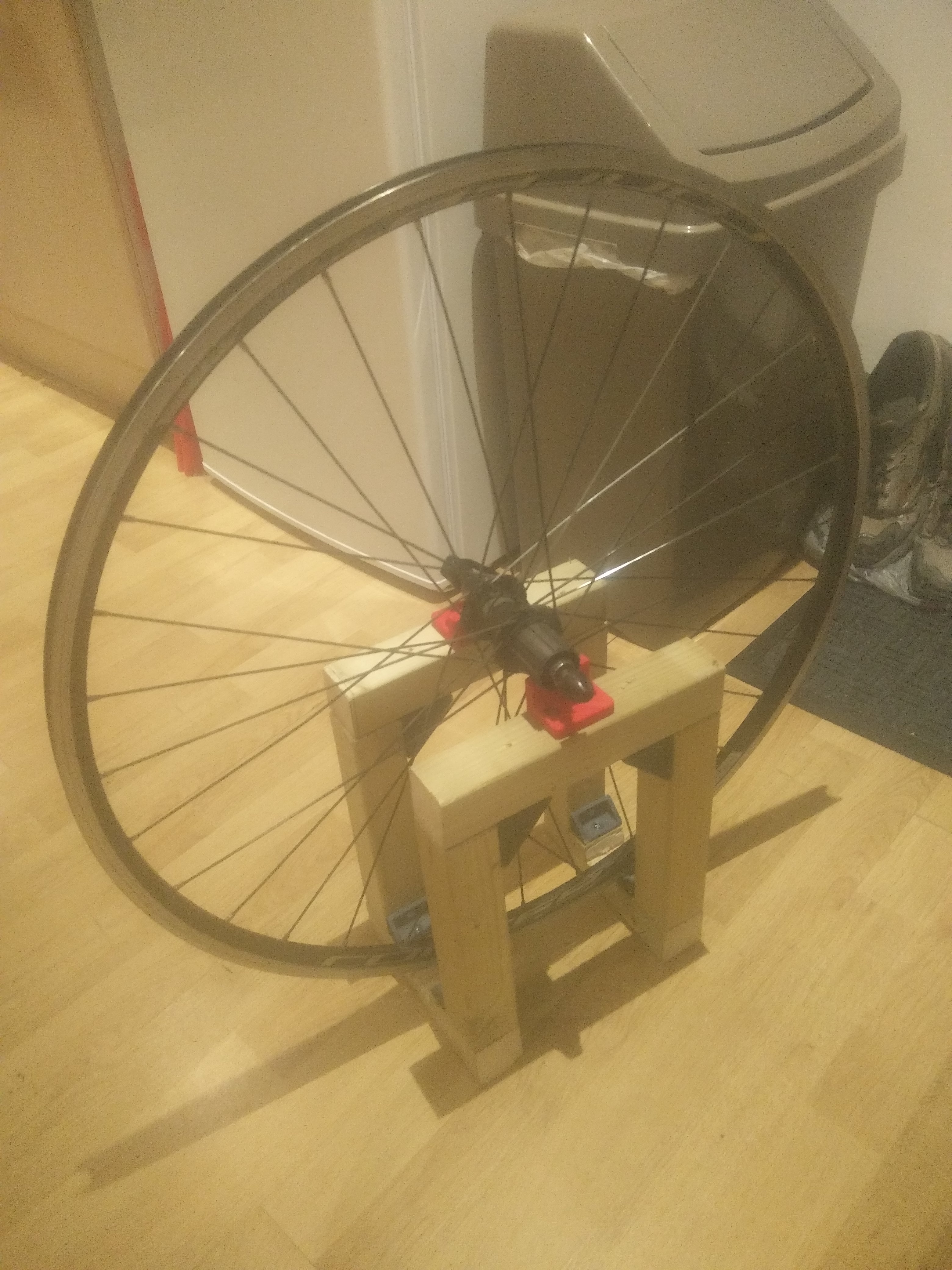
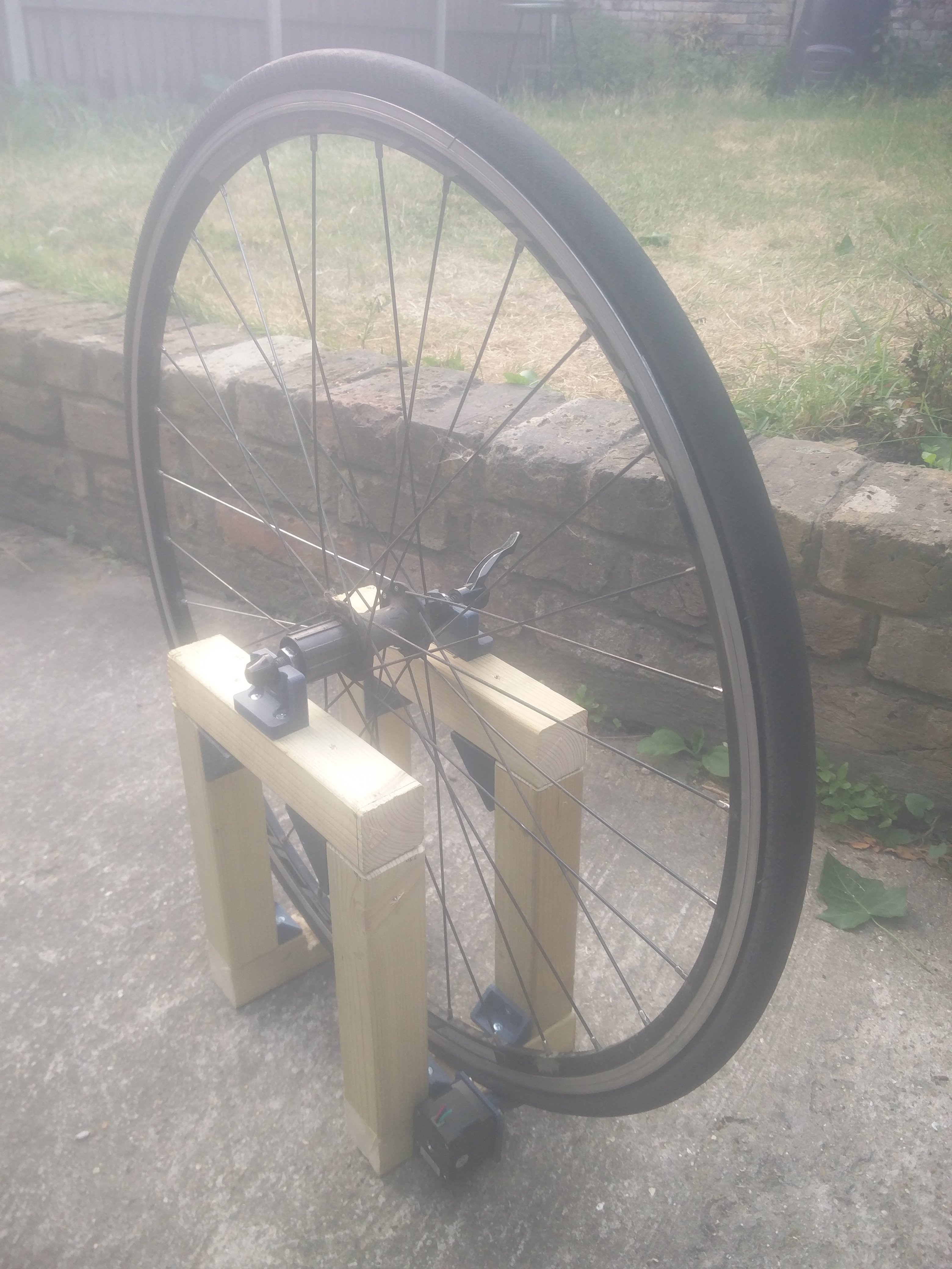
I then re-designed, 3D printed and fixed the new mounts to the frame which worked great! Although the frame isn't that stiff and won't be suitable for very precise measurements, I'm hoping it will be fine for the proof of concept prototype.
My initial idea for spinning the wheel was to use the tire as a spring so even if the wheel is a little out of true in the z-direction, the tire can compress as it is being rotated by the roller.
I designed the wheel roller geometry to be similar to a pulley which I thought would most effectively grip the tyre of the wheel from both sides. However, I found that due to how untrue my wheel was, there was either too much pressure when the deflated tyre was deviating to the side, or little to no pressure when the tyre was in the middle of the roller.
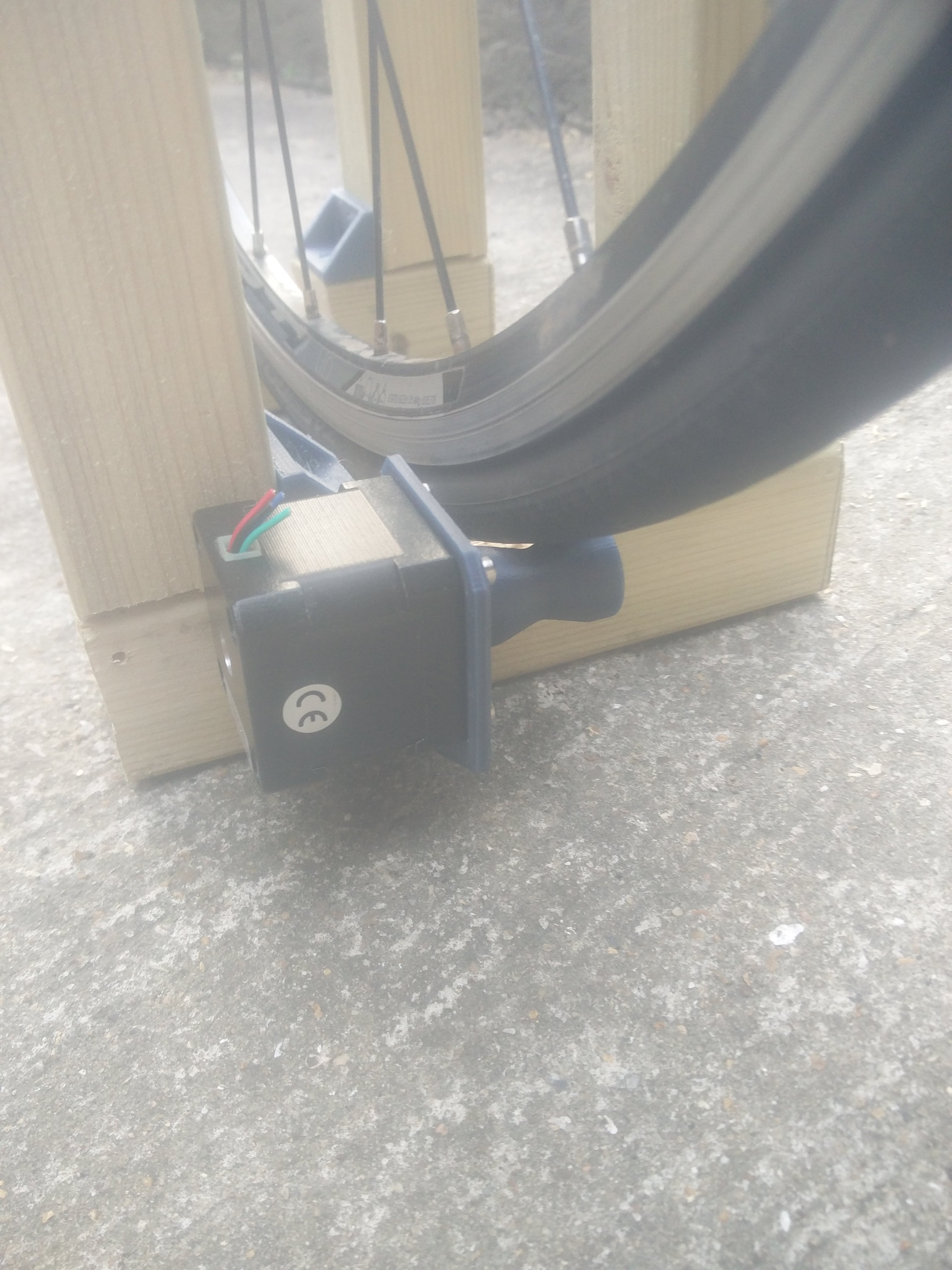
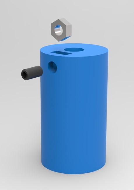
I tried a simple cylinder instead and reprinted and assembled the roller and found that it worked effectively, with the roller and tyre staying in full contact over an entire revolution. The render below shows the through hole for the motor shaft which I designed with an interference fit, a slot for the captive nut and side hole for a grub screw.
The next blog post on this topic will detail Stage 2 which will include wiring up and mounting the electronics as well as creating a semi-automated wheel truing process.
Contact Me About This Post
Subscribe to Blog Updates
Enter your email to receive notifications when new posts are published.